This project adds a small microphone and amplifier circuit to one of the analogue inputs to allow the system to monitor sound levels in a room.
The use of a sound level device can be very good for keeping the peace in a shared space, not everyone knows how much noise they’re making, so something like this can give a subtle indication when things are getting a bit rowdy. If noise levels become excessive then something even less subtle could be started.
The circuit consists of a high gain audio amplified and a half-wave rectifier and smoother. The input of the circuit is a regular condenser microphone. The output is a DC voltage that varies between 0 and 0.5 volt, representing the current amount of noise in the room.
The output of the audio circuit is connected to one of the analogue inputs of the Nime Computer.
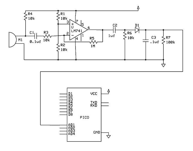
The analogue to digital converter in the Nime Computer will return a whole number reading of 0 for zero volts to 1023 for 3 volts input. Therefore, a 0 to 0.5v input would give readings in the range of 0 to 170.
The program to run this will need to operate on this range and decide what is quiet, acceptable and too loud!
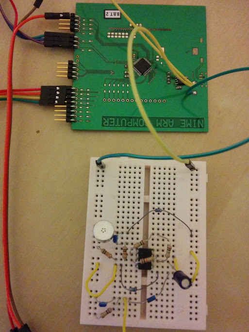
The picture below shows the breadboard construction of the amplifier circuit. It will operate from the same supply as the Nime Computer, 3 volts and ground.
The test program below will list on the console, the highest sound value it detects. If the user presses the ‘r’ key, the maximum value will be reset. The SYS(12) call is used to read the AD1 input.
5 max=0
10 a = SYS(12,100)
20 IF a>max THEN GOSUB 500
30 k=INKEY(0)
40 IF k="r" THEN max=0
100 GOTO 10
500 max=a
510 PRINT max
520 RETURN
